Principal Component Analysis To Decompose Signals and Reduce Dimensionality (codes included)
Principal Component Analysis is a technique that can extract the dominant pattern in the data matrix in terms of a set of new orthogonal variables called principal components and the corresponding set of factor scores based on its dominance (e.g. Kutz 2013; Abdi & L. J. Williams 2010). Some of its applications includes data compression, image processing, exploratory data analysis, pattern recognition, time series prediction etc.
The data matrix contains the observations that are described by several inter-correlated quantitative dependent variables. The main goals of PCA are to extract the most important information (may not be most dominant) from the data matrix, compress the size of data matrix by removing orthogonal components that explains less variance for the data. The PCA computes principal components, the new set of variables, that are linear combinations of original variables. The principal components are required to have estimated variance in descending order.
Key idea — rotate the axes onto the directions of greatest variance. PCA finds a new set of orthogonal axes — the principal components — where the first points along the direction the data spreads out most, the second along the next-most (perpendicular to the first), and so on. Rank them by variance and the top few usually capture almost everything, so you can reconstruct or compress the signal with just a handful of modes. In practice you get them from the singular value decomposition of the data matrix — which is exactly what makes PCA the same machinery as the EOF analysis used on space–time fields.
Apply PCA on a time-space function
Let us apply PCA on a time-space function borrowed from Kutz (2013).
Create a function
\[f(x, t) = [1 - 0.5 \cos 2t]\, \mathrm{sech}\, x + [1-0.5 \sin 2t]\, \mathrm{sech}\, x \tanh x\]Solutions of the form equation above are often obtained in myriad of contexts by full numerical simulations of underlying physical system.
import numpy as np
import matplotlib.pyplot as plt
from scipy import linalg
plt.style.use('seaborn')


x = np.linspace(-10,10,100)
t = np.linspace(0,10,30)

[X,T]=np.meshgrid(x,t)

def sech(X):
    return 1/np.cosh(X)

f=sech(X)*(1-0.5*np.cos(2*T))+(sech(X)*np.tanh(X))*(1-0.5*np.sin(2*T))


vmin = np.amin(f)
vmax = np.amax(f)


from matplotlib import cm
from mpl_toolkits.mplot3d import Axes3D

fig = plt.figure(figsize=plt.figaspect(0.8))
ax = fig.gca(projection='3d')
# Plot the surface.
surf = ax.plot_surface(T, X, f, cmap='summer',linewidth=0, antialiased=True, rstride=1, cstride=1, alpha=None)
ax.set_ylabel(r'$X$')
ax.set_xlabel(r'$T$')
surf.set_clim(vmin,vmax)
plt.colorbar(surf)
plt.tight_layout()
plt.savefig('PCA_space_time_func.png',dpi=300,bbox_inches='tight')
plt.close('all')
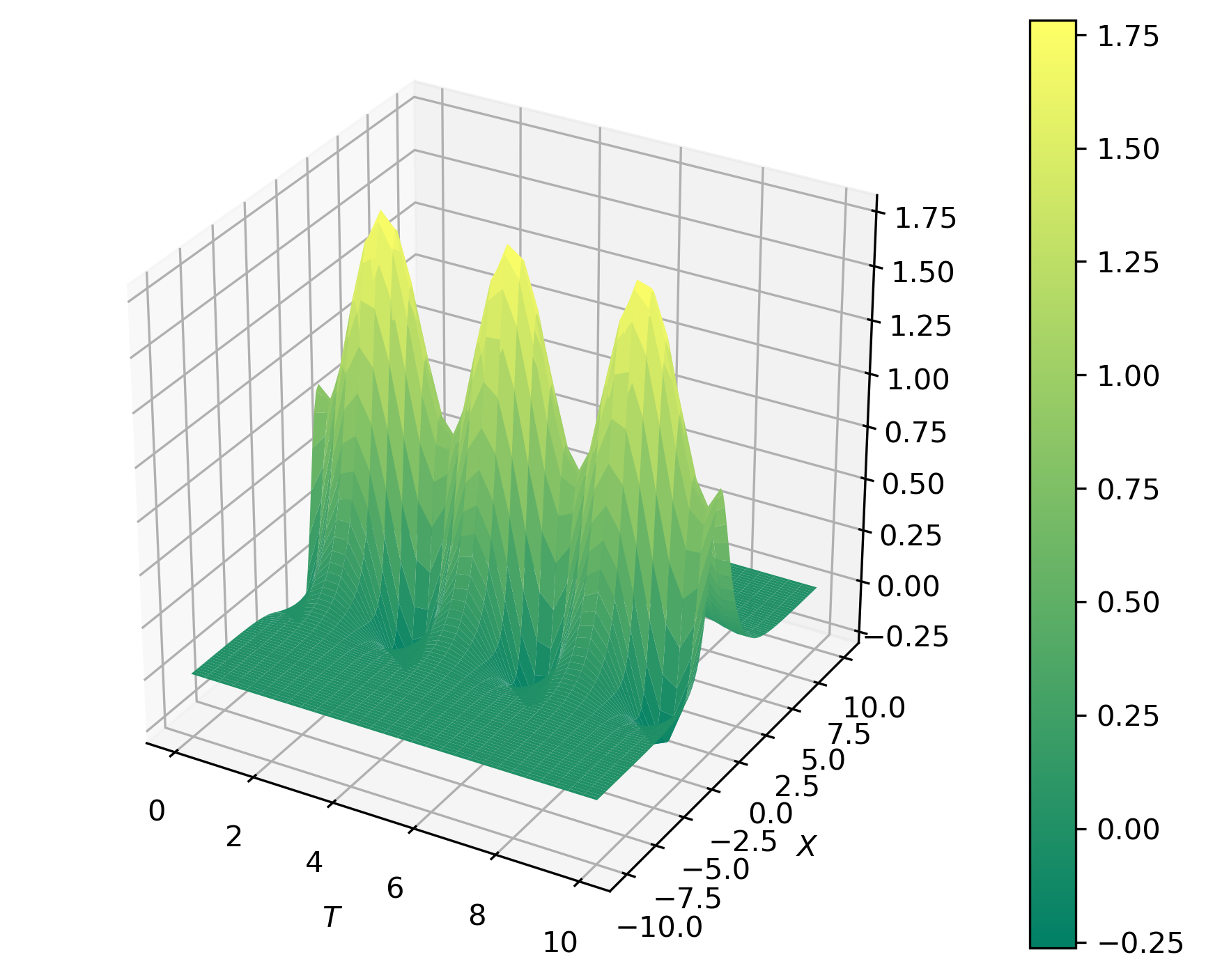
Two Matplotlib updates for a current install. (1) fig.gca(projection='3d') no longer works — passing keyword arguments to gca() was removed in Matplotlib 3.6. Create the 3-D axes with ax = fig.add_subplot(projection='3d') instead. (2) plt.style.use('seaborn') was removed in 3.8 — use 'seaborn-v0_8'. The scipy.linalg.svd decomposition itself is unchanged.
Compute the PCA
We can apply PCA to investigate the dynamics of this system.
u,s,v = linalg.svd(f, full_matrices=False,check_finite=False)
eigen_values = s
s = np.diag(s)

pca_modes = []
for j in range(1,3):
    ff=u[:,0:j].dot(s[0:j,0:j]).dot(v[0:j,:])
    pca_modes.append(ff)


vmin = np.min([np.amin(pca_modes[0]),np.amin(pca_modes[1])])
vmax = np.max([np.amax(pca_modes[0]),np.amax(pca_modes[1])])
Plot the Spatial Pattern
## Spatial behaviour
fig = plt.figure(figsize=plt.figaspect(0.5))
for jj in range(len(pca_modes)):
    ax = fig.add_subplot(1, 2, jj+1, projection='3d')
    surf = ax.plot_surface(T, X, pca_modes[jj], cmap='summer',linewidth=0, antialiased=True, rstride=1, cstride=1, alpha=None)
    surf.set_clim(vmin,vmax)
    ax.set_ylabel(r'$X$')
    ax.set_xlabel(r'$T$')
    ax.set_title('Var explained: {:.2f}%'.format(eigen_values[jj]/np.sum(eigen_values)*100))

plt.colorbar(surf)
plt.subplots_adjust(hspace=0.5,wspace=0.05)
plt.tight_layout()
plt.savefig('PCA_space_time_func_modes.png',dpi=300,bbox_inches='tight')
plt.close('all')
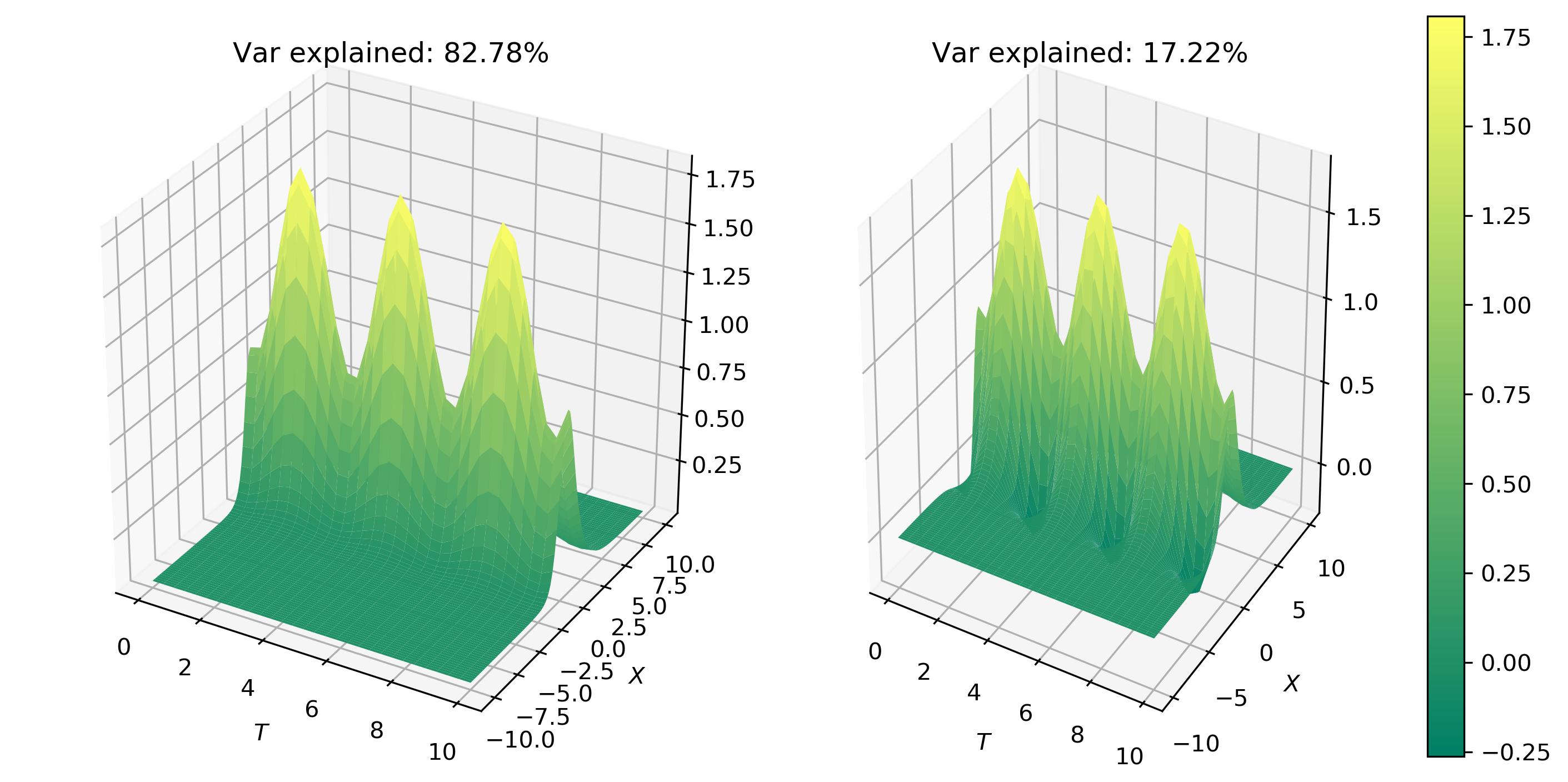
The first two modes capture 100% of the total surface energy in the system. Hence, the third mode is completely unnecessary. This suggests that system can be easily and accurately represented by a simple two-mode expansion.
A precise note on “variance explained.” The s returned by svd are the singular values. The variance each mode explains is proportional to the squared singular values, so the exact fraction for mode $i$ is $s_i^2 / \sum_j s_j^2$ (this is what the EOF/PCA literature calls percentage variance). The code above uses s / sum(s) as a quick proxy, which ranks the modes correctly but isn’t the strict variance percentage — square the singular values if you need the exact number.
Figure 2 shows the spatial behavior of the first two modes.
Quick check: The svd gives u, s, v. To keep only the first two PCA modes, why does the code use u[:,0:j] @ s[0:j,0:j] @ v[0:j,:]?
Plot the temporal pattern
## temporal behaviour
fig, ax = plt.subplots(2,1,figsize=plt.figaspect(0.5))
ax[0].plot(x,v[0,:],'k-',label='mode 1')
ax[0].plot(x,v[1,:],'k--',label='mode 2')
ax[0].set_xlabel('x')
ax[0].set_ylabel('PCA modes')
ax[0].legend()


ax[1].plot(t,u[:,0],'k-',label='mode 1')
ax[1].plot(t,u[:,1],'k--',label='mode 2')
ax[1].set_xlabel('x')
ax[1].set_ylabel('PCA modes')
ax[1].legend()

plt.subplots_adjust(hspace=0.5,wspace=0.05)
plt.tight_layout()
plt.savefig('PCA_space_time_behaviour.png',dpi=300,bbox_inches='tight')
plt.close('all')
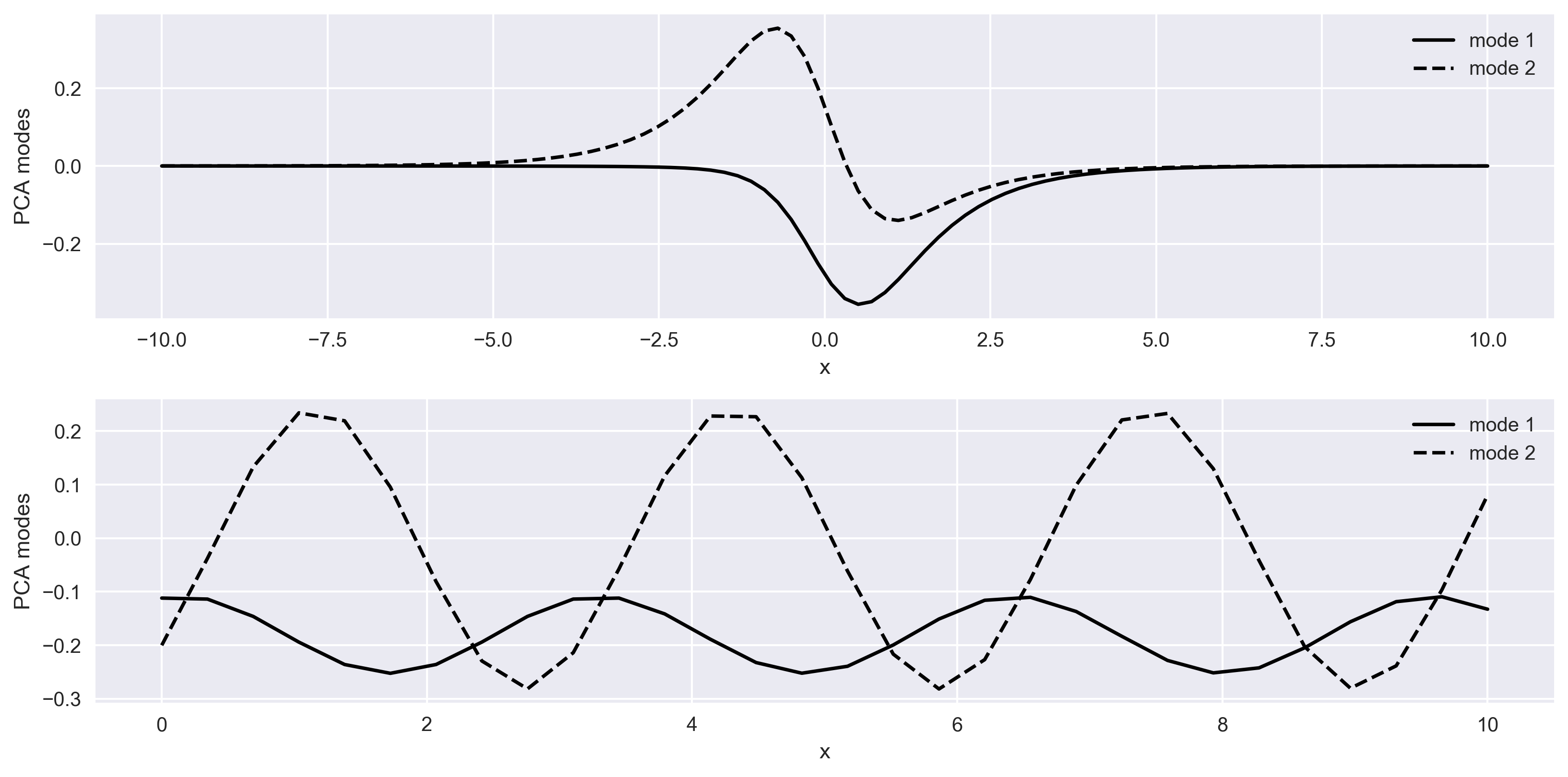
In Figure 3, top panel shows the spatial behaviour of the system for the two modes, and bottom panel shows the temporal evolution of the system for two modes.
Complete Code
Recap
- PCA = new axes along maximum variance. The principal components are orthogonal directions ranked by how much of the data’s spread they capture.
- SVD does it in one line.
u, s, v = svd(f)gives the modes; a truncated productu[:,:j] s[:j,:j] v[:j,:]reconstructs the signal from the top-$j$ modes. - Few modes, most of the signal. Here two modes captured 100% of the energy, so the field compresses to a two-mode expansion with no loss.
- Variance uses squared singular values. The exact percentage is $s_i^2 / \sum s_j^2$.
- Same math as EOF. Run this on a space–time field and PCA is EOF analysis.
Where to go next
- EOF analysis (PCA on a space–time field): Empirical Orthogonal Function analysis
numpy.linalg.svddocs: numpy.org/doc/stable/reference/generated/numpy.linalg.svd.htmlsklearn.decomposition.PCA(a batteries-included API): scikit-learn.org — PCA
References
- Principal component analysis — Abdi, H., & Williams, L. J., 2010, Wiley Interdisciplinary Reviews: Computational Statistics, 2(4), 433–459.
- Kutz, J. N. (2013). Data-driven modeling & scientific computation: methods for complex systems & big data. Oxford University Press.
Disclaimer of liability
The information provided by the Earth Inversion is made available for educational purposes only.
Whilst we endeavor to keep the information up-to-date and correct. Earth Inversion makes no representations or warranties of any kind, express or implied about the completeness, accuracy, reliability, suitability or availability with respect to the website or the information, products, services or related graphics content on the website for any purpose.
UNDER NO CIRCUMSTANCE SHALL WE HAVE ANY LIABILITY TO YOU FOR ANY LOSS OR DAMAGE OF ANY KIND INCURRED AS A RESULT OF THE USE OF THE SITE OR RELIANCE ON ANY INFORMATION PROVIDED ON THE SITE. ANY RELIANCE YOU PLACED ON SUCH MATERIAL IS THEREFORE STRICTLY AT YOUR OWN RISK.
Leave a comment