How to plot great circle path through your region using PyGMT
Introduction
Seismic tomography images the Earth’s interior from the waves that cross it — and what a wave tells you about the subsurface depends on the path it travelled, the “great circle path” between source and receiver. For a tomography study of one region, you don’t want every path; you want the paths that actually pass through your region of interest. This article shows how to find and plot exactly those, using PyGMT together with NumPy, Pandas, Shapely, and Pyproj.
The one mental model
A great-circle path is the shortest route between two points on a sphere — the line a seismic ray roughly follows. To pick the useful ones, the script does a simple test per station:
sample the source→receiver arc as points → does the arc enter your region polygon? → keep it, else skip.
Only paths that cross your region carry information about the rocks beneath it.
Install PyGMT
Using a Python venv
python -m venv geoviz
source geoviz/bin/activate
pip install pygmt
For more details, visit the article A Quick Overview on Geospatial Data Visualization using PyGMT.
Install note: PyGMT is a wrapper around the GMT C library (it needs GMT ≥ 6.5), so
pip install pygmt only works if GMT is already on your system. The officially recommended route is
conda/mamba, which installs GMT and PyGMT together:
mamba install --channel conda-forge pygmt.
Plot great-circle paths traversing the region of interest
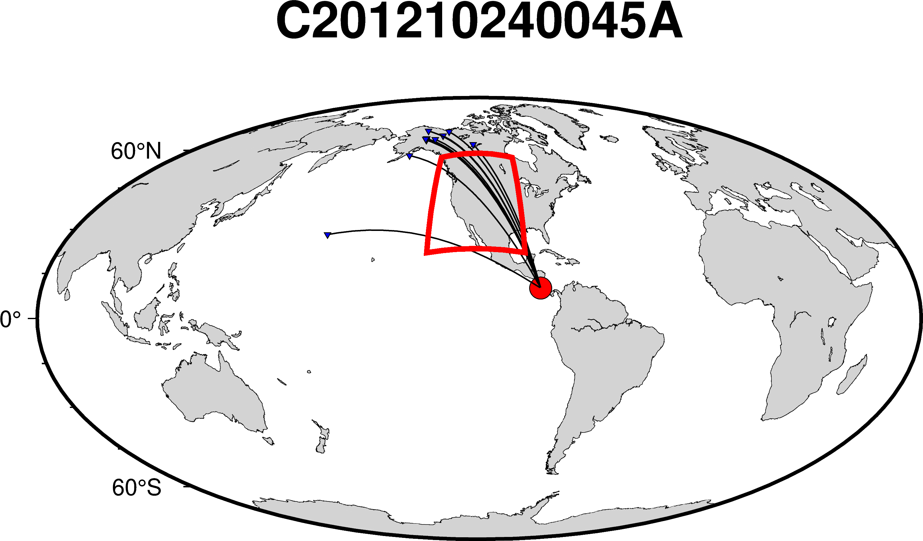
This script reads earthquake-event and seismic-station data, filters them by location, and plots the great-circle paths between the source and each station on a high-resolution map — using Shapely and Pyproj to decide whether each path traverses the region of interest.
import pygmt
import numpy as np
import pandas as pd
import yaml, glob, os, sys
from shapely.geometry.polygon import Polygon
import pyproj
from shapely.geometry import Point


def get_region_polygon(
    # Box size
    lon_left   = -128,      # possible range: -180, 180 deg
    lon_right  = -96,      # possible range: -180, 180 deg
    lat_bottom = 27,      # possible range: -90, 90 deg
    lat_top    =  52,      # possible range: -90, 90 deg
    offset = 20, # offset in degrees from the box limits
):
    lon_left  = lon_left - offset
    lon_right = lon_right + offset
    lat_bottom = lat_bottom - offset
    lat_top = lat_top + offset

    box_lims = [[lon_left,lat_bottom], [lon_right,lat_bottom], [lon_right,lat_top], [lon_left,lat_top], [lon_left,lat_bottom]]
    box_maxdim = max(np.abs(lon_right-lon_left),np.abs(lat_top-lat_bottom))
    lims_array = np.array(box_lims)
    boxclon, boxclat = np.mean(lims_array[:, 0]),np.mean(lims_array[:, 1])
    box_polygon = Polygon(box_lims)

    return box_polygon

def is_in_domain(lon_points, lat_points, box_polygon):

    for lat, lon in zip(lat_points, lon_points):
        # print(lon, lat)
        if box_polygon.contains(Point(lon,lat)):
            return True
    return False


def main():

    ## Inversion domain
    lon_left = -128      # possible range: -180, 180 deg
    lon_right = -96      # possible range: -180, 180 deg
    lat_bottom = 27      # possible range: -90, 90 deg
    lat_top =  52      # possible range: -90, 90 deg

    ## Event info
    evbase = 'C201210240045A' # (D12O0TUA)
    evlon = -85.30
    evlat = 10.09
    evdep = 17.0
    evmag = 6.0


    ## Define polygon
    box_polygon = get_region_polygon(offset = 5)
    print("box_polygon.bounds: ",box_polygon.bounds)
    geod=pyproj.Geod(ellps="WGS84")

    out_image_station = f"{evbase}.png"

    ## plot stations
    fig = pygmt.Figure()
    projection = "W-110.5885/12c"
    fig.basemap(region='g', projection=projection, frame=["afg", f"+t{evbase}"])
    fig.coast(
        land="lightgrey",
        water="white",
        shorelines="0.1p",
        frame="WSNE",
        resolution='h',
        area_thresh=10000
    )

    if is_in_domain([evlon], [evlat], box_polygon):
        print(f"--> Skipping {evbase} because it is in domain")

    dff_event = pd.read_csv('event_station_info_D12O0TUA.txt', sep='\s+', header=None, names=['evname', 'stn', 'slon', 'slat'])
    # print(dff_event)

    assert len(dff_event) > 0, "No stations found in event_station_info_D12O0TUA.txt"

    fig.plot(x=evlon, y=evlat, style="c0.3c", color="red", pen="black")

    for stlat, stlon, sname in zip(dff_event.slat, dff_event.slon, dff_event.stn):
        if is_in_domain([stlon], [stlat], box_polygon):
            continue
        line_arc=geod.inv_intermediate(evlon,evlat,stlon,stlat,npts=300)
        lon_points=np.array(line_arc.lons)
        lat_points=np.array(line_arc.lats)
        if not is_in_domain(lon_points, lat_points, box_polygon):
            continue
        fig.plot(x=lon_points, y=lat_points, pen="0.5p,black")
        fig.plot(x=stlon, y=stlat, style="i0.1c", color="blue", pen="black")


        rectangle = [box_polygon.bounds]
        fig.plot(data=rectangle, style="r+s", pen="2p,red")

    print('----> Saving map... {}'.format(out_image_station))
    fig.savefig(out_image_station, crop=True, dpi=600)

if __name__ == "__main__":
    main()
Download the event_station_info_D12O0TUA.txt from here
PyGMT version note: recent PyGMT (v0.12+) renamed the color parameter to fill in plotting
methods like fig.plot(...). The script above still runs with a deprecation warning on current
versions; on new code, use fill="red" / fill="blue" instead of color=....
How the selection works
The logic is a straightforward per-station filter, built from three libraries: Pyproj computes the great-circle arc, Shapely tests whether it hits the region, and PyGMT draws the survivors.
The key line is geod.inv_intermediate(evlon, evlat, stlon, stlat, npts=300), which samples the
source→receiver great circle into 300 points. is_in_domain(...) then asks Shapely whether any of
those points falls inside the region polygon — if so, the path (and its station) are plotted; if not,
they’re skipped. Stations that sit inside the region are also skipped, since a path that starts in
the region doesn’t cross into it from outside.
Why does the script sample each great-circle arc into 300 points before testing it?
Recap
Without scrolling up — can you describe the workflow? To plot great-circle paths through a region:
- Define the region as a polygon (Shapely),
- For each station, compute the source→receiver great-circle arc (Pyproj
geod), sampled into many points, - Keep the path only if the arc enters the polygon, and
- Draw the surviving paths and stations with PyGMT.
That filter is what turns a full station list into just the ray paths that actually sample the crust and mantle beneath your study area.
Where to go next
- PyGMT documentation — plotting methods and the
fill/penstyling options. - Related post here: A Quick Overview on Geospatial Data Visualization using PyGMT.
Disclaimer of liability
The information provided by the Earth Inversion is made available for educational purposes only.
Whilst we endeavor to keep the information up-to-date and correct. Earth Inversion makes no representations or warranties of any kind, express or implied about the completeness, accuracy, reliability, suitability or availability with respect to the website or the information, products, services or related graphics content on the website for any purpose.
UNDER NO CIRCUMSTANCE SHALL WE HAVE ANY LIABILITY TO YOU FOR ANY LOSS OR DAMAGE OF ANY KIND INCURRED AS A RESULT OF THE USE OF THE SITE OR RELIANCE ON ANY INFORMATION PROVIDED ON THE SITE. ANY RELIANCE YOU PLACED ON SUCH MATERIAL IS THEREFORE STRICTLY AT YOUR OWN RISK.
Leave a comment